Introduction
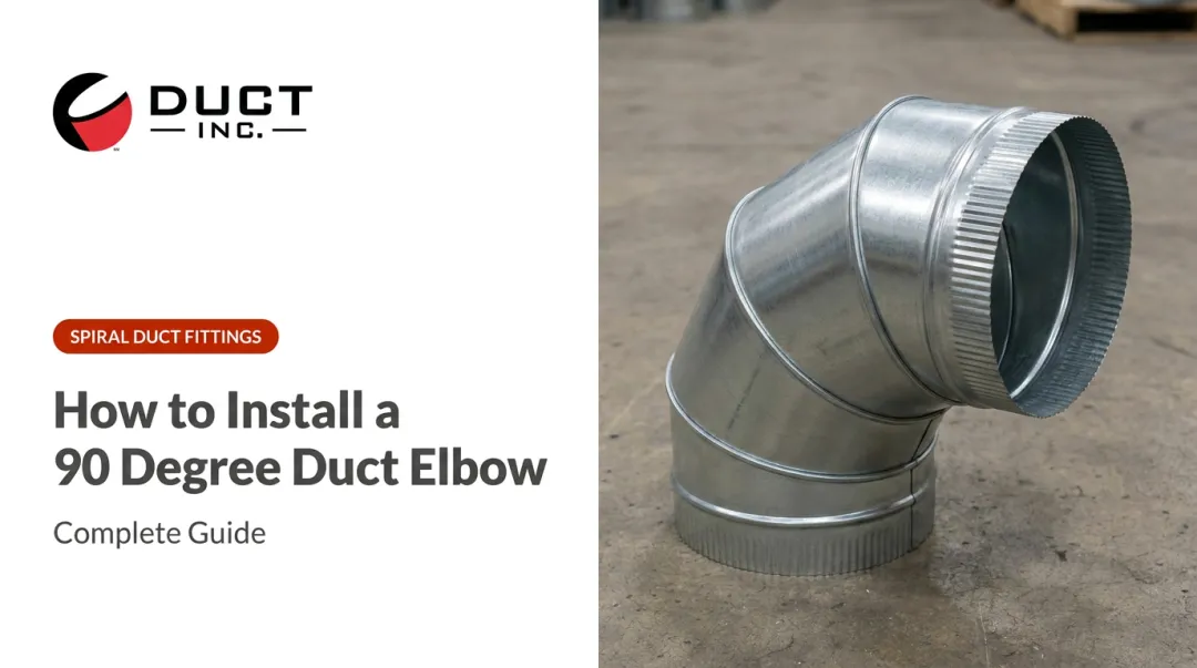
An industrial duct system can be perfectly sized for airflow — correct diameter, appropriate velocity, right fan capacity — and still underperform. The culprit is often hiding in plain sight: too many high-resistance 90° elbows, or the wrong elbow type specified for a critical run.
Fittings routinely account for the majority of total pressure drop in industrial duct systems. A single hard-mitered 90° elbow without turning vanes can carry a loss coefficient nearly 8× higher than a smooth long-radius elbow — and in a system with five or six elbows on the critical path, that gap can add dozens of equivalent feet to your critical path before you've accounted for a single straight run.
This guide breaks down what equivalent length means for 90° duct elbows, which variables drive those values, and how elbow selection feeds into total effective length (TEL) calculations — the foundation for sizing the rest of the system.
Key Takeaways
- A 90° elbow's pressure drop is expressed as an equivalent length of straight duct: the length of pipe that produces identical resistance at the same flow conditions
- Smooth long-radius elbows can outperform hard-mitered elbows by 5× or more in equivalent length — elbow geometry has an outsized effect on system resistance
- The R/D ratio (turn radius to duct diameter) is the dominant variable — higher R/D means gentler turn, lower resistance
- More elbow pieces (5-piece vs. 3-piece) produces smoother airflow and lower loss coefficients
- Fittings — not straight duct runs — are the primary driver of total system resistance in most industrial layouts
What Is Equivalent Length and Why 90° Elbows Matter
The Core Concept
Equivalent length is the length of straight duct that would produce the same pressure drop as a given fitting at identical flow conditions. This lets designers work in a single unit — feet of duct — when accounting for both straight runs and fittings during system calculations.
The method comes directly from equating two loss equations:
- Fitting dynamic loss: ΔP = C × Pv (loss coefficient × velocity pressure)
- Straight duct friction loss: ΔP = f × (L/D) × Pv
Setting these equal and solving for L yields: Le = C × D / f
So equivalent length scales with the fitting's loss coefficient (C) and duct diameter (D), and shrinks as the friction factor (f) increases. A mitered elbow, with a high C value, carries a long equivalent length; a well-radiused elbow with a low C value carries a short one.
Why Fittings Dominate Straight Runs
In a long straight run, friction losses accumulate gradually. In a fitting, airflow abruptly changes direction — creating turbulence and flow separation that dissipate energy across a very short physical distance.
The DOE Fan Systems Sourcebook illustrates the scale of this effect: placing an elbow too close to a fan outlet can reduce delivered airflow by up to 30%, driven entirely by fitting placement rather than duct sizing. In real industrial systems, straight duct sections may span 30–50 feet, while the fittings on that same run can represent hundreds of equivalent feet of resistance.
Equivalent Length vs. Total Effective Length
These terms are related but distinct:
- Equivalent length (EL): The resistance of a single fitting, expressed as straight duct footage
- Total effective length (TEL): The sum of all fitting equivalent lengths plus all measured straight duct lengths in a complete duct run
TEL is what gets used to calculate the friction rate and size the duct. Confusing the two — or applying TEL logic to individual fittings — leads directly to undersized duct and higher-than-expected static pressure.
Key Factors That Determine a 90° Elbow's Equivalent Length
The R/D Ratio
The R/D ratio is the centerline radius of curvature (R) divided by the duct diameter (D). A higher R/D ratio means the air follows a more gradual arc, which reduces turbulence and lowers the loss coefficient significantly.
ASHRAE's Fitting Loss Coefficients data for smooth round 90° elbows (Fitting 3-1) shows this directly:
| R/D Ratio | Loss Coefficient (C) |
|---|---|
| 1.0 | 0.22 |
| 1.5 | 0.15 |
| 2.0 | 0.13 |
| 2.5 | 0.12 |

Going from R/D 1.0 to R/D 2.0 cuts the loss coefficient nearly in half. Since equivalent length scales proportionally with C, that difference translates directly into a shorter equivalent length and lower system resistance.
Practical guidance: Specify elbows with R/D ≥ 1.5 wherever space allows. On the critical path run, this single decision can reduce elbow resistance by 30–45%.
Number of Pieces in Segmented Elbows
Segmented elbows approximate a smooth curve through a series of angled sections. More pieces produce a smoother airflow path and lower resistance. ASHRAE Fitting 3-2 provides coefficients for segmented round 90° elbows:
| Pieces | R/D 1.0 | R/D 1.5 | R/D 2.0 |
|---|---|---|---|
| 3-piece | 0.42 | 0.34 | 0.33 |
| 4-piece | 0.37 | 0.27 | 0.24 |
| 5-piece | 0.33 | 0.24 | 0.19 |
At R/D 1.5, a 5-piece elbow has a coefficient of 0.24 versus 0.34 for a 3-piece — a 29% reduction in resistance.
Some designers deliberately specify a 3-piece elbow knowing that if installers upgrade to a 5-piece, the system will outperform the design. This builds a conservative buffer into calculations without over-sizing duct.
Round vs. Rectangular Duct
ASHRAE's Duct Fitting Database covers more than 220 round, rectangular, and flat oval fittings, each with separate coefficient tables. Mixing coefficient tables across duct shapes is a common field error that leads to under-estimated system resistance. Key rules:
- Round vs. rectangular: Rectangular duct generates corner vortices through bends, increasing resistance relative to round duct at the same nominal geometry — never share equivalent length values between the two
- Flat oval: Oval duct elbows have their own dedicated tables; applying round duct values to oval configurations consistently underestimates resistance
- General rule: Always match the fitting type and shape to the correct ASHRAE table — no cross-referencing between duct geometries
Equivalent Length Values for Common 90° Elbow Types
Understanding the Loss Coefficient Table
The ASHRAE primary source data provides dimensionless loss coefficients (C), not equivalent lengths in feet. Actual equivalent length depends on duct diameter and friction factor per the relationship Le = C × D / f. The relative performance differences are clear from the coefficients alone.
| Elbow Type | Loss Coefficient (C) | Relative Resistance |
|---|---|---|
| Smooth round, R/D 2.0 | 0.13 | Lowest |
| Smooth round, R/D 1.5 | 0.15 | Very low |
| Smooth round, R/D 1.0 | 0.22 | Low |
| 5-piece segmented, R/D 1.5 | 0.24 | Low-moderate |
| 3-piece segmented, R/D 1.5 | 0.34 | Moderate |
| Round mitered, no vanes | 1.20 | Very high |

Sources: ASHRAE Fitting Loss Coefficients, Fittings 3-1, 3-2, 3-3.
The mitered elbow without turning vanes (C = 1.2) carries a coefficient roughly 8× higher than a smooth long-radius elbow at R/D 2.0 (C = 0.13). In a duct system where five elbows appear on the critical path, that difference multiplies into hundreds of equivalent feet of additional resistance.
Calculating Equivalent Length from First Principles
When published tables don't cover your exact fitting geometry, you can derive equivalent lengths directly from your system parameters. The method is:
- Obtain the loss coefficient C from ASHRAE or SMACNA tables for your specific fitting
- Determine the duct friction factor f for your diameter and velocity
- Apply: Le = C × D / f (with consistent units)
This approach is also used to validate code-compliant duct designs. For example, dryer exhaust duct sizing per the IRC and IMC uses this method to confirm that a given elbow configuration stays within the maximum equivalent length allowed for the run.
A Note on Velocity Calibration
Published equivalent length tables are calibrated at specific reference velocities. At lower velocities — increasingly common in systems with variable-speed drives or ECM blowers — equivalent lengths need to be adjusted. Applying table values calibrated at high velocities to low-velocity systems without correction will underestimate resistance, leading to under-sized ducts or insufficient airflow.
Always verify what velocity the reference table was calibrated at, and apply correction factors when your design velocity differs significantly.
How Equivalent Length Fits Into Total Effective Length Calculations
The Step-by-Step Process
TEL calculation follows a defined sequence:
- Map the complete duct system — document all branches, runs, and fittings
- Assign equivalent lengths — use ASHRAE or SMACNA tables to assign an EL value to each fitting on each run
- Sum each run — add fitting ELs to measured straight duct lengths for each complete run
- Identify the critical path — the run with the highest TEL is the design run; this is not the sum of all runs combined

The critical path run sets the friction rate for the entire system. Every other branch must be balanced against it.
From TEL to Friction Rate
Once TEL is established, the designer calculates the available friction rate:
Friction Rate = Available Static Pressure ÷ (TEL / 100)
This friction rate — expressed in inches of water column per 100 feet — is then used with a friction chart or duct calculator to size each duct section. SMACNA Duct Design Fundamentals identifies starting friction rate ranges of 0.08–0.15 in. wg/100 ft for energy-cost-sensitive designs and 0.30–0.60 in. wg/100 ft where installation cost is the primary constraint.
The Impact of a Single Elbow Choice
That friction rate budget is highly sensitive to fitting choices. Consider a critical path run with 80 feet of straight duct and four 90° elbows:
- Scenario A (smooth elbows, R/D 1.5): 4 elbows × ~15 ft EL = 60 ft + 80 ft straight = 140 ft TEL
- Scenario B (mitered elbows, no vanes): 4 elbows × ~75 ft EL = 300 ft + 80 ft straight = 380 ft TEL
That single substitution — mitered for smooth — nearly triples the TEL, collapsing the friction rate budget and forcing larger duct diameters across every section tied to the critical path.
Selecting the Right 90° Elbow to Minimize Pressure Loss
Performance Hierarchy
From best to worst for pressure performance:
- Smooth long-radius (R/D ≥ 2.0) — lowest resistance, ideal for critical path runs where space permits
- Smooth long-radius (R/D 1.5) — excellent performance, fits tighter spaces
- 5-piece segmented — strong alternative when a drawn radius elbow isn't available
- 4-piece segmented — moderate resistance, acceptable for non-critical branches
- 3-piece segmented — higher resistance, use on low-velocity or non-critical runs
- Mitered with turning vanes — significantly better than hard mitered; acceptable in space-constrained installations
- Mitered without turning vanes — highest resistance, avoid on any critical path run

Practical Selection Rules
- Default to R/D ≥ 1.5 whenever physical space in the installation allows
- In tight spaces, a mitered elbow with turning vanes is far preferable to one without — the AMCA Impact of Fitting Selection documents significant pressure penalties for mitered elbows without vanes
- Never place a hard mitered elbow (no vanes) directly off a fan outlet — close-coupled elbows at fan discharge create system effects that can reduce delivered airflow by up to 30%
- These principles apply equally to round, flat oval, and rectangular configurations, though the specific values differ by duct geometry
For specifiers putting these selection rules into practice, Duct Incorporated manufactures industrial spiral duct elbows from 3" to 80"+ in galvanized, galvaneal, stainless steel 304/316, and aluminum — with their elbow product line covering both standard catalog configurations and custom fabrication for non-standard R/D ratios. Their design assistance resources support system resistance calculations during the specification process.
Frequently Asked Questions
What is the typical equivalent length of a standard 90° duct elbow?
Equivalent length varies widely by elbow type and duct diameter. A hard-mitered elbow without vanes carries a loss coefficient of 1.2 per ASHRAE — roughly 8× higher than a smooth elbow at R/D 2.0 (C = 0.13). Always verify values against ASHRAE or SMACNA fitting tables for your specific geometry and velocity.
How does the R/D ratio affect a 90° elbow's equivalent length?
A higher R/D ratio means the air follows a gentler arc through the bend, which reduces turbulence and lowers the fitting's loss coefficient (C). Since equivalent length scales directly with C, a higher R/D ratio produces a shorter equivalent length. ASHRAE data shows the smooth 90° elbow loss coefficient drops from 0.22 at R/D 1.0 to 0.13 at R/D 2.0 — making R/D ratio the single most important variable in elbow selection.
What is the difference between equivalent length and total effective length (TEL)?
Equivalent length is the resistance of one individual fitting expressed as straight duct footage. TEL is the sum of all fitting equivalent lengths plus all measured straight duct lengths across a complete duct run. TEL represents the entire resistance of the critical path and is what you divide available static pressure by to determine the design friction rate.
Does using more 90° elbows significantly affect HVAC system performance?
Yes. Each additional 90° elbow adds to the critical path's equivalent length, and the effect compounds with each fitting. In many industrial duct systems, fittings account for 50–70% of total system resistance — far more than the straight duct runs between them.
Do equivalent length values change based on air velocity in the duct?
Yes. Published tables are calibrated at specific reference velocities. At lower velocities — common with variable-speed drives or ECM blower systems — apply the correction factors in your design reference; skipping this step underestimates resistance and produces undersized duct.
Are equivalent length values the same for round and rectangular 90° elbows?
No. Round and rectangular duct elbows have entirely separate fitting coefficient tables. Rectangular elbows typically carry higher resistance than round elbows at comparable geometries due to secondary flow effects at the corners. Oval duct elbows also have their own separate tables — applying round duct values to oval or rectangular configurations is a consistent source of underestimated system resistance.