The core problem is that engineers often treat tee fittings as simple junctions. They're not. Every tee forces flow through a direction change, a momentum split, and turbulent mixing — all of which consume energy irreversibly.
This guide covers what drives tee branch pressure drop, how the branch and run paths differ, proven calculation methods, and practical design strategies to control losses before they become a commissioning headache.
Key Takeaways
- Branch pressure drop is consistently higher than run pressure drop, often by a factor of 5 or more under identical flow conditions
- Pressure drop scales with velocity squared: cutting velocity in half reduces tee losses by 75%
- Acute-angle wye fittings can reduce branch loss coefficients by 65% or more compared to standard 90° tees
- Standard K-factor tables apply only to fully turbulent flow in line-sized tees; both conditions must be met for accurate results
- Flow split calculations require iteration until both legs show equal pressure drop
What Is Pressure Drop Through a Tee Branch Fitting?
When flow enters a tee junction, it must split, change direction, decelerate, and re-accelerate — all within a short length of duct. Each of those events dissipates energy. The result is an irreversible energy loss expressed as a pressure drop (ΔP), formally classified as a minor loss in fluid mechanics.
The "minor" label is misleading. As NIST Technical Note 2206 notes, pressure losses from fittings are conventionally called minor losses but can be as significant as major (friction) losses in HVAC and plumbing systems — particularly in compact duct runs with many junctions.
Major losses vs. minor losses:
- Major losses — friction along straight pipe or duct runs, calculated using the Darcy-Weisbach equation
- Minor losses — energy dissipation at fittings, junctions, valves, and any point where flow geometry changes abruptly
Tees generate more resistance than most other common fittings because they combine two loss mechanisms at once: the branch path forces a full direction change, while both paths must manage the momentum redistribution as flow splits. Per Idelchik's Handbook of Hydraulic Resistance, four distinct mechanisms drive these losses — none of which a simple elbow fully replicates:
- Turbulent mixing — chaotic energy exchange where the branch and main flows collide
- Stream curvature — centrifugal pressure gradients as flow bends into the branch
- Shock loss — sudden momentum transfer at the point of flow division
- Flow separation — boundary layer detachment along the inner fitting wall

Flow Paths Through a Tee: Branch vs. Run
Every standard tee has two distinct outflow paths, and they behave very differently.
- The run — the straight-through path with minimal direction change. Flow continues largely undisturbed, losing relatively little energy.
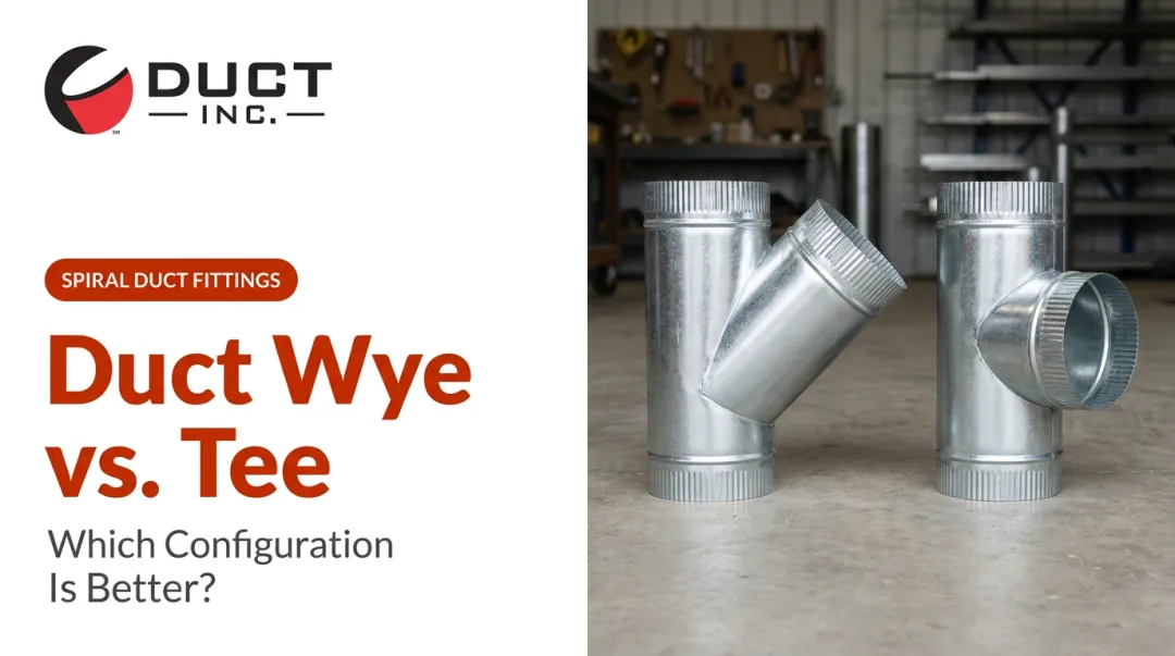
- The branch — the 90° (or angled) turn into the side connection. Flow must decelerate, turn, and re-accelerate, consuming significantly more energy.
For a 90° converging round tee at moderate flow split conditions, ASHRAE fitting loss coefficient data shows a branch coefficient of 0.52 versus a run coefficient of 0.08 — the branch path is more than six times lossier under those conditions.
Understanding which path dominates a system starts with identifying how flow actually moves through the junction.
The Four Flow Patterns at a Tee Junction
The applicable calculation method depends entirely on flow direction. The four patterns are:
- Diverging from header — one inlet divides into run and branch outlets
- Converging into header — branch and one header leg combine into a single outlet
- Dividing from branch — a branch splits flow in two opposite header directions
- Combining into branch — two opposing header flows merge into the branch
Each pattern has its own set of loss coefficients. Using diverging coefficients for a converging junction — or vice versa — will produce meaningless results.
Tee Geometry and Branch Angle
Geometry has a quantifiable effect on branch loss. ASHRAE round diverging fitting data shows:
- Branch coefficient at 90°: 1.4 (for Ab/Ac = 0.5, Qb/Qc = 0.5)
- Branch coefficient at 45°: 0.40 (same area and flow ratio)
That's a 71% reduction in branch loss coefficient simply by changing the branch entry angle. Idelchik's Table 7-3 confirms this trend with angle correction factors ranging from 0.04 at 15° to 1.0 at 90°.
In converging tees, certain low-flow-split conditions produce negative loss coefficients. This happens when the higher-velocity stream transfers kinetic energy to the lower-velocity stream during mixing, resulting in a net pressure gain for one path — even though the junction as a whole still dissipates energy.
ASHRAE fitting tables include these cases explicitly. They are not calculation errors.
How to Calculate Pressure Drop in Tee Branch Fittings
The K-Factor Method
The standard approach for tee pressure drop uses the loss coefficient (K-factor):
ΔP = K × (ρV²/2)
Where:
- K = dimensionless loss coefficient for the specific path (run or branch)
- ρ = fluid density (kg/m³ or lb/ft³)
- V = mean velocity in the reference duct or pipe
The K-factor is referenced to a specific velocity basis defined by the coefficient table — always confirm which cross-section the table uses before applying a value.
Crane Technical Paper 410 is the most widely cited source for pipe fitting K-factors in the process industries. For tee fittings, TP-410 uses K values scaled to f_T (the Moody friction factor for fully turbulent flow).
Secondary sources reference K = 20f_T for the run path and K = 60f_T for the branch. Verify these values against the licensed TP-410 tables rather than relying on secondary citations alone.
Important caveat on scatter: NIST TN 2206 reports K-factor variations of 2% to 161% for fittings with the same nominal diameter and material from different manufacturers. Treat published K-values as reference data, not as guaranteed installed performance.
The Equivalent Length Method
The equivalent length (Le/D) approach treats a fitting's pressure drop as equivalent to additional straight duct of the same diameter. Commonly referenced values are approximately Le/D = 20 for the tee run and Le/D = 60 for the branch, though sources vary — verify the specific values from the reference applicable to your system (Crane TP-410, ASHRAE Handbook of Fundamentals, or similar).
This method works well for preliminary sizing, but the K-factor approach is more accurate for detailed design. The walkthrough below applies that method to a standard diverging tee.
Step-by-Step Calculation for a Diverging Tee
For a tee with one inlet splitting into run and branch outlets:
- Identify flow rates — determine Q for the run leg and branch leg
- Calculate velocity in each leg: V = Q/A
- Select K-factors — separate values for run and branch paths
- Calculate ΔP per path: ΔP = K × (ρV²/2) for each leg
- Check the governing path — both share the same inlet pressure; the higher-ΔP path governs system design

When flow split is unknown, the calculation requires iteration. The correct split is the one that produces equal pressure drop in both legs at the junction node — flow split affects velocity, velocity affects K-factor application, and ΔP must balance before results are valid.
Key Factors That Affect Tee Branch Pressure Drop
Flow Velocity
Pressure drop scales with velocity squared. Double the velocity and ΔP quadruples. This relationship, embedded directly in the ΔP = K(ρV²/2) formula, means that modest velocity increases create disproportionate losses, particularly in branch paths already carrying high K-factor penalties.
Branch Angle and Internal Geometry
Acute branch angles reduce K-values dramatically. Sharp interior corners create flow separation and recirculation zones that elevate losses; rounded entries stabilize the flow and minimize those zones, as Idelchik documents.
For high-flow industrial duct applications, the difference between a sharp-corner tee and a smooth-entry wye is not marginal. Depending on the angle, it can change the branch loss coefficient by an order of magnitude.
Flow Split Ratio
The proportion of total flow diverted to the branch directly determines branch velocity, and thus branch ΔP. A branch carrying 70% of system flow at high velocity will have losses far exceeding what a simple K-factor lookup suggests, because the underlying velocity term dominates.
Fitting Size and Diameter Ratio
Standard K-factor tables are calibrated for line-sized tees — meaning the branch diameter equals the run diameter. As that ratio increases, the coefficients become less reliable. For large diameter mismatches, the standard tee model breaks down and alternative loss models are required. Consult the specific fitting manufacturer's data or use pipe flow simulation software that applies corrections outside standard correlation ranges.
Flow Regime
Standard K-factor data assumes fully turbulent flow. At lower Reynolds numbers — laminar or transitional flow — loss coefficients for branch fittings increase substantially. Standard values can substantially underestimate actual pressure drop in those conditions.
Two methods account for Reynolds-number dependence when turbulent flow cannot be assumed:
- Hooper's 2-K method (Chemical Engineering, 1981) — incorporates both a turbulent-flow coefficient and a Reynolds-number correction term
- Darby's 3-K method (Chemical Engineering Fluid Mechanics, 2nd ed., 2001) — adds a fitting-size correction for greater accuracy across diameter ranges
Either method is preferable to standard K-factor lookups whenever laminar or transitional conditions are present.
How to Minimize Pressure Drop Through Tee Branch Fittings
Three design decisions have the most leverage on tee branch losses:
1. Choose acute-angle wye fittings over 90° tees where layout allows
The ASHRAE data cited above supports this directly: a 45° branch entry reduces the branch loss coefficient from 1.4 to 0.40 under equivalent conditions. ACGIH industrial ventilation guidance similarly recommends 30° to 45° branch entry angles for industrial exhaust systems to minimize energy loss. Where space permits, wye configurations with acute branch angles should be the default selection for high-flow branch connections.
2. Specify fittings with defined internal geometry
The manufacturer-to-manufacturer variation documented by NIST (up to 161% for the same nominal size and material) means generic K-factors can be significantly wrong for a specific installed fitting. Specifying precision-manufactured fittings with consistent, documented internal geometry ensures actual performance is predictable across the system.
Duct Incorporated's branch fitting line covers this requirement directly:
- Tee and Y-configurations in galvanized, galvaneal, stainless steel 304/316, and aluminum
- Diameter range: 3" to 80"+
- LaserLock modular options for quick-assembly installations
- Custom fabrication for non-standard configurations

3. Design the flow split at the system level, not the fitting level
Branch pressure drop is a network-level problem. Sizing each branch fitting independently — without simultaneously designing the flow split and header sizing — produces systems that require extensive downstream damping to balance, and those dampers add their own pressure drop. Designing the flow split, branch sizing, and header velocities together produces a more balanced system with lower total losses and less reliance on mechanical balancing devices.
That system-level approach also informs tool selection. For complex networks with many tee junctions, iterative hand calculation becomes impractical — flow simulation tools based on Idelchik and Miller can resolve coupled flow splits automatically. Note that the simplified (lossless) tee model in these tools is only appropriate when tee losses are genuinely small relative to total system resistance; convergence issues can arise in large networks if that assumption doesn't hold.
Frequently Asked Questions
What is the difference between tee run pressure drop and tee branch pressure drop?
The run (straight-through path) has a much lower loss coefficient than the branch because flow continues with minimal direction change. The branch path forces fluid to decelerate, turn 90°, and re-accelerate, consuming substantially more energy in the process. ASHRAE data shows branch coefficients typically 5–10 times higher than run coefficients for standard tee geometries.
Why is the K-factor for a tee branch so much higher than for the run?
The 90° direction change causes flow to separate from the inner wall of the branch, creating turbulent recirculation that dissipates energy; run flow continues relatively undisturbed. Per Crane TP-410, the branch path K-factor (referenced as ~60fT) is roughly three times the run path value (~20fT). Verify these constants against the licensed TP-410 tables before applying them.
How do I calculate pressure drop when flow divides at a tee?
Calculate ΔP separately for the run and branch legs using each leg's own velocity. The correct flow split is found iteratively: find the flow division that produces equal pressure drop in both legs at the junction node. Start with an assumed split, calculate both ΔPs, then adjust until they converge.
Can I use standard tee K-factors for a tee with a much smaller branch than the main run?
Standard K-factors apply to line-sized tees where branch and run diameters match. For large diameter mismatches, the standard coefficients become unreliable; use alternative loss models or manufacturer-specific data instead. Idelchik, Miller, or the fitting manufacturer's documentation provide guidance outside standard correlation ranges.
What equivalent length should I use for a tee branch in duct calculations?
Commonly referenced values are approximately Le/D = 20 for the run and Le/D = 60 for the branch, though sources vary and some references give different run values. Always verify against the specific reference applicable to your system — Crane TP-410 or ASHRAE Handbook of Fundamentals — rather than relying on secondary tables.
Does flow regime affect tee branch pressure drop calculations?
Yes, significantly. Standard K-factor tables are calibrated for fully turbulent flow. In laminar or transitional flow, loss coefficients increase substantially and standard values will underestimate actual pressure drop. Use Hooper's 2-K method or Darby's 3-K method when turbulent flow cannot be assumed.