
The concept sounds straightforward: exhaust contaminated air, bring clean air in. The reality involves precise calculations, component sequencing, duct routing, compliance checks, and material selection decisions that compound on each other. Skip or rush any one step and the whole system suffers.
This guide walks through the complete design process — from site assessment to commissioning — plus system type selection, the four parameters that determine real-world performance, common design errors, and a structured troubleshooting framework.
BLS data shows private industry reported 54,000 respiratory illness cases in 2024, reinforcing that airborne hazard control isn't optional. A well-designed exhaust system is one of the most effective engineering controls available.
Key Takeaways
- Every design follows six steps — from site assessment and CFM calculation through fan selection and compliance verification
- Four variables determine worker protection: air change rate, CFM, static pressure, and make-up air balance
- LEV and dilution ventilation are not interchangeable — choosing the wrong type is the most common and expensive design mistake
- OSHA and EPA compliance must be built into the design from day one, not patched in after installation
How to Design an Industrial Exhaust System: Step-by-Step
Step 1: Conduct a Site and Process Assessment
Start by mapping the facility layout and identifying every contaminant source. Document:
- Contaminant type — dust, chemical vapor, heat, smoke, metal fumes
- Generation volume and frequency — continuous vs. intermittent emissions
- Proximity to breathing zones — distance from source to nearest worker
- Facility characteristics — ceiling height, occupancy, equipment placement, number of workers

Document structural constraints as well: existing ductwork, available roof penetrations, wall openings, and column locations. These determine what routing is physically possible before any calculations begin. Designers who skip this step routinely misplace hoods and undersize branch ducts — the primary driver behind most industrial ventilation retrofit projects.
Step 2: Calculate Ventilation Requirements
The standard volumetric airflow formula is:
CFM = (Room Volume in cubic feet × Air Changes per Hour) ÷ 60
Air changes per hour (ACH) vary by facility type. Secondary engineering references cite ranges such as foundries at 15–20 ACH and paint shops at 10–15 ACH, but treat these as screening values only. For hazardous contaminants, ACGIH emphasizes contaminant-specific hood, capture velocity, and duct calculations over generic ACH targets.
The CFM figure from this formula drives every downstream decision: duct sizing, fan selection, filter specification, and make-up air volume. An undersized CFM baseline means every component downstream will be selected against flawed inputs — and correcting that after installation typically costs more than the original system.
Step 3: Select the Right System Type
Two primary system architectures exist:
- Local exhaust ventilation (LEV) — captures contaminants at the source using hoods and targeted ductwork before they disperse into the workspace
- Dilution/general exhaust ventilation — floods the space with fresh air to reduce concentration across the entire room
ACGIH states that LEV is generally preferred because it captures contaminants at the source and reduces the volume of tempered replacement air required. Dilution is only appropriate when LEV is impractical.
Use LEV when: contaminants are toxic, generated at identifiable point sources, or near worker breathing zones (welding, grinding, solvent use, chemical processing).
Dilution may be acceptable when: contaminants are low-toxicity, uniformly distributed, and generated by mobile sources like forklifts — but it falls dangerously short for dusts, metal fumes, and high-toxicity vapors.
Hybrid systems combining both approaches are common in larger facilities with multiple zones and different contamination profiles.
Step 4: Design the Ductwork Layout
Duct sizing is driven by transport velocity — the minimum air speed required to keep particulates suspended and moving without settling. ACGIH Table 3-2 defines minimum duct design velocities by contaminant category:
| Contaminant Type | Minimum Duct Velocity |
|---|---|
| Vapors, gases, smoke | 1,000–2,000 fpm (economic optimum) |
| Welding fumes | 2,000–2,500 fpm |
| Very fine light dusts | 2,500–3,000 fpm |
| Dry dusts and powders | 3,000–4,000 fpm |
| Average industrial dusts (grinding, silica, foundry) | 3,500–4,000 fpm |
| Heavy dusts (metal turnings, sandblast, wet sawdust) | 4,000–4,500 fpm |
| Heavy or moist contaminants | 4,500 fpm and above |

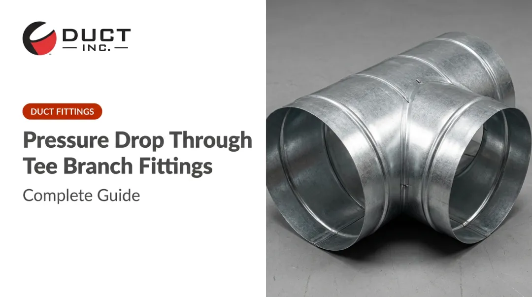
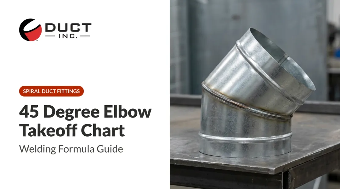
When routing ductwork, minimize elbows, transitions, and total run length — each fitting adds static pressure loss. Longer-radius elbows (1.5× to 2× pipe diameter) reduce turbulence and pressure drop significantly compared to short-radius bends. For facilities specifying fittings across a wide diameter range, Duct Incorporated offers elbows, reducers, and transitions from 3 inches to 80 inches, with design assistance to match fitting configurations to your system layout.
Make-up air is non-negotiable. OSHA's construction ventilation standard requires outside air at 90%–110% of exhaust volume for each room with exhaust hoods. Without adequate make-up air, the facility develops negative pressure, exhaust effectiveness drops, and contaminated outdoor air gets pulled in through gaps and unsealed penetrations.
Step 5: Select Fans and Air Cleaning Equipment
Fan selection requires two inputs working together: required CFM and total system static pressure.
- Axial fans suit high-volume, low-pressure applications — general warehouse exhaust, for example
- Centrifugal fans handle higher static pressure drops in longer duct runs or systems with filtration equipment; radial impellers are preferred for heavy particulate loading
- Explosive or combustible dust environments require spark-resistant or explosion-proof fan construction per NFPA 91 and NFPA 654
Air cleaning equipment selection depends on contaminant type and discharge regulations:
| Device | Typical Pressure Drop | Best Fit |
|---|---|---|
| Baghouse/fabric filter | 5–20 in. w.g. | Bulk particulate, dusts |
| HEPA filter | ~1.0–1.5 in. w.g. (initial) | Fine/submicron particulate |
| Wet scrubber (medium energy) | 5–25 in. w.g. | Particulate + acid gases |
| Dry electrostatic precipitator | Low | Fine particulate, PM2.5 |
Each device's pressure drop must be added back into total static pressure before finalizing fan selection. A fan sized to the duct system alone — without accounting for filter resistance — will be undersized at the actual operating point.
Step 6: Verify Compliance and Commission the System
Cross-check the completed design against:
- OSHA 29 CFR 1910.94 — ventilation for abrasive blasting, grinding, spray finishing, open surface tanks
- OSHA 1926.57 — construction ventilation including LEV duct velocity requirements (4,500 fpm in branch ducts for grinding/abrasive operations)
- NFPA 91 — exhaust systems conveying vapors, gases, mists, and particulate solids
- NFPA 654 — fire and explosion prevention for combustible particulate solids
- EPA Clean Air Act regulations — for discharge stack emissions
Commission by measuring actual airflow at each hood and duct branch using an anemometer or pitot-tube traverse. Compare results against design CFM targets and document a baseline for future maintenance comparisons. OSHA also recommends smoke tubes and hood face velocity checks during startup.
Critical Design Parameters That Affect System Performance
The difference between a system that meets compliance minimums and one that genuinely protects workers at full production comes down to four variables.
Air Change Rate (ACH)
ACH must match the specific process — running one air change short of the required rate allows contaminants to accumulate over a full shift. Build a 10–20% buffer above the calculated minimum to accommodate production variability and future process additions.
When production scales up or new equipment is added, ACH requirements change, and an undersized system won't signal the problem until worker exposure climbs. ACH tells you how much air to move — static pressure determines whether the fan can actually deliver it.
Static Pressure
Static pressure is the total resistance the fan must overcome through the entire duct network. Every section of duct, every elbow, every transition, every filter adds resistance:
Total static pressure = hood entry losses + duct friction losses + fitting losses + equipment pressure drops
The fan's performance curve must be checked against the system resistance curve to confirm the actual operating point. A fan that cannot overcome total static pressure delivers far less airflow than its rated CFM — sometimes dramatically less — causing system failure that may not be immediately visible. OSHA recommends six duct diameters of straight duct at the fan inlet and three at the outlet to minimize system effect losses at the fan connection.

Capture Velocity and Hood Design
For LEV systems, hood capture velocity must overcome ambient air currents and pull contaminants in before they reach the worker's breathing zone.
- General capture hoods (minimum): 50 fpm per OSHA OTM
- Welding fumes (exterior hoods): 100–170 fpm per ACGIH recommendations cited in NIOSH literature
Hood shape, size, and placement are just as important as fan sizing. As a general rule, exterior capture hoods should be positioned no farther than one hood diameter from the emission source — beyond that distance, capture velocity drops off sharply and contaminants escape into the breathing zone.
Hood geometry matters as much as proximity — a flanged hood increases capture efficiency by roughly 25% compared to a plain opening at the same airflow, which can meaningfully reduce the required fan size. Duct Incorporated offers custom and suction hoods for LEV applications, designed around specific process requirements rather than off-the-shelf dimensions.
Make-Up Air Temperature and Volume Balance
Make-up air deficiencies of even 15–20% create measurable negative pressure that reduces fan effectiveness and exposes workers to cold drafts in winter — driving up energy costs and generating comfort complaints that obscure the underlying ventilation problem.
Make-up air must be:
- Supplied at 90%–110% of exhaust volume to maintain neutral building pressure
- Drawn from a clean intake at least 10 feet from exhaust discharge points to prevent re-entrainment of exhausted contaminants
- Conditioned seasonally — heated in winter, cooled in summer — to prevent extreme temperature exposure for workers near supply diffusers
Common Mistakes in Industrial Exhaust System Design
Most ventilation failures trace back to a small set of recurring errors — and they tend to appear during the design phase, not after installation. Catching them early prevents expensive retrofits.
Skipping the site assessment: Rule-of-thumb calculations without mapping actual contaminant sources, ceiling heights, and structural constraints produce hoods in the wrong locations and branch ducts at the wrong sizes — the root cause of most retrofits.
Treating make-up air as an afterthought: Focusing entirely on exhaust capacity while leaving make-up air unplanned creates negative pressure, reduces airflow, and allows cold outdoor air to infiltrate through building gaps. This issue shows up repeatedly in industrial hygiene audits.
Selecting fans by CFM alone: A fan's rated CFM is only achievable at a specific static pressure. Ignoring system static pressure during selection puts the fan's operating point far down its curve, delivering a fraction of intended airflow at full power draw.
Adding duct branches without rebalancing: Every new branch redistributes airflow across the entire network — remote hoods lose capture velocity as a result. Any modification requires a full system rebalancing assessment, not just a check of the new branch alone.

Troubleshooting Common Industrial Exhaust System Problems
Even well-designed systems develop problems over time. A structured diagnostic approach catches issues before they become worker exposure incidents.
Reduced Airflow at Hood Openings
Likely causes:
- Clogged filters or baghouse
- Particulate settled in duct bends (transport velocity fell below minimum)
- New duct branches added since original installation, redistributing airflow
What to check: Measure hood face velocity with an anemometer against commissioning baseline. Inspect and replace filters. Check duct interior at bends for settled material. Rebalance branch dampers if the system has been modified.
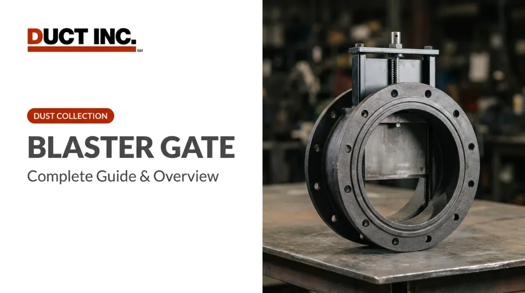
For systems that have been modified or expanded, slide gates and dampers at branch points give you precise control over rebalancing — isolating individual branches without disrupting the rest of the network.
Excessive Noise or Vibration from Fan
Likely causes:
- Belt wear or misalignment (belt-drive fans)
- Bearing failure
- Particulate buildup on fan blades causing rotational imbalance
- Fan operating at a different point on its curve than designed
What to check: Inspect belts, bearings, and blade surfaces. Clean blades and recheck balance. Verify total system static pressure hasn't changed significantly since installation. Confirm all dampers and access panels are in designed positions.
Persistent Odors or Contaminants Reaching Worker Breathing Zone
Likely causes:
- Hood positioned too far from emission source
- Make-up air supply directing contaminated air toward workers
- System running below required ACH due to an underlying airflow deficiency
What to check:
- Re-measure hood capture velocity against design spec
- Review make-up air inlet locations relative to exhaust discharge points and worker positions
- Check whether operational changes — new equipment, higher production volume — have pushed contaminant output past the system's original design capacity
Frequently Asked Questions
What are the main types of industrial ventilation systems?
The two primary types are local exhaust ventilation (LEV), which captures contaminants at the source using hoods and ductwork, and dilution (general) ventilation, which reduces concentration by circulating large volumes of fresh air through the space. Hybrid systems combining both are common in large or multi-zone facilities.
How do you calculate CFM for an industrial exhaust system?
CFM = (Room Volume in cubic feet × Required Air Changes per Hour) ÷ 60. The result must then be validated against hood capture velocity requirements and adjusted to account for total system static pressure — the raw CFM figure alone is insufficient for final component sizing.
What is make-up air and why does it matter?
Make-up air is the fresh air supplied to replace the volume being exhausted. Without it, the facility develops negative pressure, exhaust effectiveness drops, and contaminated air can be drawn back in through gaps and openings. OSHA requires make-up air at 90%–110% of exhaust volume.
What is the difference between LEV and dilution ventilation?
LEV captures contaminants at the point of generation and is the preferred choice for toxic or high-volume pollutants. Dilution ventilation mixes contaminated air with fresh air across the entire space, making it appropriate only for low-toxicity, uniformly distributed pollutants where source capture is impractical.
What OSHA standards apply to industrial exhaust system design?
OSHA 29 CFR 1910.94 covers ventilation for abrasive blasting, grinding, spray finishing, and open surface tanks. OSHA 1926.57 applies to construction-site ventilation. Designs must also comply with applicable NFPA standards (NFPA 91, NFPA 654) for hazardous environments and EPA regulations governing discharge stack emissions.
How do you select the right fan for an industrial exhaust system?
Fan selection requires matching required CFM to total system static pressure using the fan's performance curve, not CFM alone. Contaminant characteristics then determine fan construction: standard, spark-resistant, explosion-proof, or corrosion-resistant, based on whether the airstream carries explosive dust, corrosive vapors, or high-temperature gases.