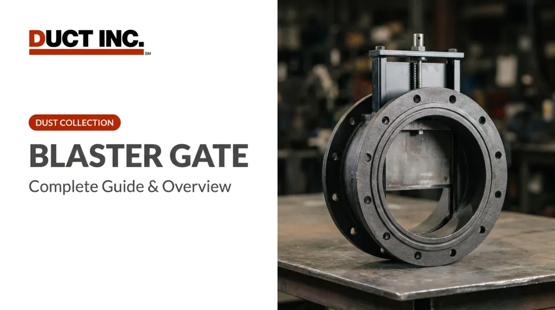
According to Processing Magazine, blast gates adjusted even slightly change airflow performance across every other hood in the system — which means a single poorly installed or leaking gate degrades the entire network. In grit environments specifically, using the wrong gate material compounds the problem: standard plastic gates wear rapidly, fail to seal, and can jam entirely under abrasive loading.
This guide covers the complete process — gate selection, mechanical installation, actuator integration, and post-installation validation — with a clear focus on what to do and what not to skip.
Key Takeaways
- Grit blast gates require steel or cast iron bodies — standard plastic gates fail in metalworking and grinding dust environments
- Identify your automation trigger type (starter circuit, current relay, or PLC) before choosing an actuator
- Actuator alignment is the most common cause of binding and incomplete travel — get it right before final fastening
- Airtight duct joints and full open/close travel must be verified before returning the system to service
- Gate size must match branch duct diameter exactly — undersizing restricts flow, oversizing causes sealing failures
Installation Guide for Grit Blast Gates
Grit blast gate installation follows four stages: gate selection and site preparation → mechanical mounting into ductwork → actuator and control integration → validation and commissioning.
Mechanical installation of a single gate typically takes one to two hours per drop. Automation integration adds time depending on the number of gates, actuator type, and control complexity. Plan for a full day when commissioning a multi-gate system for the first time.
Prerequisites and Safety
Before ordering anything or cutting ductwork, confirm the following:
- Duct diameter at each installation point — measure the internal diameter at each branch location; this is your gate size, not the nominal label on the pipe
- Automation infrastructure available — check whether compressed air lines are accessible near each gate (for pneumatic actuators) or whether the machine starter circuit is accessible (for electric actuators). Mismatched infrastructure is why installations stall mid-project
- System de-energized and locked out — OSHA's lockout/tagout standard (29 CFR 1910.147) requires all hazardous energy to be controlled before servicing; no exceptions
- Combustible dust classification — if the application involves metallic fines (aluminum, magnesium, titanium), confirm compliance with NFPA 484 before proceeding; metallic dusts carry explosion risk that changes system design requirements
Do not install standard plastic or light-duty blast gates in ductwork carrying metallic grit, grinding dust, or abrasive particulate. Only gates with steel or cast iron blades and hardened seat surfaces belong in grit environments.
Duct Incorporated's slide gate and blast gate damper range is built for these applications — dust collection, mining, cement processing, and pneumatic conveying. Contact our technical team to confirm the right gate specification for your system at ductincorporated.com/contact-us.
Tools and Parts Required
For all installations:
- Correctly sized grit blast gate matched to internal duct diameter
- Compatible flanged or slip-fit duct fittings (wyes or laterals at the branch junction)
- Sheet metal screws or duct flange hardware
- Pipe sealant or gasket tape
- Drill with sheet metal bits
- Deburring tool
For automated installations, add:
- Pneumatic cylinder with solenoid valve, or electric linear actuator
- Control wiring matched to actuator voltage
- Conduit or cable management
- Multimeter for circuit verification
- For pneumatic: push-to-connect fittings and filtered airline tubing
Do not substitute the gate body or improvise actuator mounts. Undersized gates restrict flow; improvised brackets cause misalignment and binding.
How to Install Grit Blast Gates (Step-by-Step)
Skipping steps — particularly fitting alignment and actuator travel adjustment — is the most common cause of binding, leaking, and early gate failure.
Step 1 — Prepare the installation site
With the dust collector off and locked out, mark the gate location on the branch duct. Cut the duct opening to the gate's face dimensions and deburr all cut edges. Confirm the gate orientation before cutting — the blade travel direction must match the duct layout and must not conflict with adjacent fittings or supports.
Step 2 — Mount the gate into the ductwork
Slide or flange the gate body into position. Apply sealant or gasket material at every duct interface before fastening. Secure with sheet metal screws or flange bolts, but confirm the blade slides freely through its full travel before tightening final fasteners. A blade that binds before the actuator is even attached means a fitting alignment problem that gets worse, not better, under load.
Step 3 — Attach and align the actuator
Mount the pneumatic cylinder or electric actuator to the gate's actuator bracket so the actuator rod connects squarely to the gate blade. Misalignment here is a primary cause of actuator failure. Adjust the bracket position until the actuator rod travel matches the gate's full stroke exactly — both full open and full closed — before torquing any fasteners.
Step 4 — Connect the control signal
- Pneumatic actuators: plumb the solenoid valve to a dry, filtered compressed air supply and wire the solenoid coil to the machine's starter circuit or control relay
- Electric actuators: wire to the control signal, observing polarity and voltage rating
All wiring must be run in conduit or protected from abrasive debris. Exposed wiring in a grit environment fails.
Step 5 — Configure end-of-travel limits
Set end-of-travel adjustments or limit switches so the gate fully opens and fully closes without the actuator stalling or over-driving. For multi-gate systems with a PLC or central controller, assign each gate's I/O address and verify the control logic before commissioning.

Post-Installation Checks and Validation
Do not return the system to service without completing these checks:
- Suction test — with the dust collector running and all other gates closed, trigger the new gate and verify that suction at the connected machine port increases noticeably; reduced suction means an air leak at the duct joint or an incomplete open position
- Visual inspection — inspect the gate-to-duct joint for sealant gaps and confirm all fasteners are tight
- Full cycle observation — watch the actuator through a complete open-close cycle, looking for hesitation, partial travel, or mechanical binding
A gate that does not fully close allows uncontrolled air bleed that reduces system-wide suction. One that binds mid-travel only deteriorates further under abrasive grit loading. Both faults must be resolved before the system returns to service.
Common Installation Problems and Fixes
Gate Leaks Air When in the Closed Position
Problem: Audible suction or measurable airflow when the gate should be fully closed, reducing overall system performance.
Likely cause: The blade isn't reaching its hard stop, sealant was not applied at the duct joint, or grit has accumulated on the blade seat and is preventing flush contact.
Fix: Verify the actuator end-of-travel setting drives the blade all the way to the hard stop. Re-seal the duct joint. Inspect the blade seat for abrasive buildup — clean it, and if the seat surface is visibly worn, replace the blade assembly.
Actuator Does Not Complete Full Open or Close Travel
Problem: The gate blade stops partway through its stroke, leaving the gate neither properly open nor properly closed.
Likely cause: Actuator rod is misaligned with the blade connection point, the actuator lacks sufficient force for the gate size, or an end-of-travel limiter is set incorrectly.
Fix: Re-square the actuator bracket so the rod drives squarely onto the blade connection. Confirm the actuator's force rating is appropriate for the gate size and operating pressure or voltage. Reset end-of-travel limits with the gate physically at full-open and full-closed positions.
Grit Jamming the Gate Mechanism
Problem: The gate blade becomes difficult or impossible to move after a period of operation — often accompanied by actuator stall or motor overload trip.
Likely cause: Abrasive grit has packed into the blade channel or around the actuator rod seal. This happens either because the gate isn't rated for the particle size in use, or because the installation orientation allows grit to settle into the mechanism rather than fall away from it.
Fix: Address this systematically:
- Confirm the gate model is rated for the abrasive particle size in use
- Specify gates with sealed blade channels and purge provisions for coarse grit environments
- Mount gates so grit falls away from the blade channel, not into it
- Set a regular inspection and cleaning interval — don't wait for an actuator stall to signal a problem

Pro Tips for Installing Grit Blast Gates Effectively
Verify material specifications before ordering. A gate with a steel or cast iron blade and hardened seat costs more upfront but outlasts several replacement cycles of an undersized or wrong-material gate in any metalworking or grinding environment. Check the spec sheet, not just the product name.
Map the full system before starting. For multi-gate automated installations, document every gate assignment, actuator address, and control logic path before installation begins. Label each gate by machine. This is what separates a two-minute fix from a two-hour troubleshooting call when the system needs changes later.
Keep pneumatic supply air dry and filtered. Moisture and particulate in airline tubing cause solenoid valve failures that are routinely misdiagnosed as gate or actuator problems. Run the airline through a filter-regulator-lubricator (FRL) unit before it reaches the solenoid.
Use current-sensing relays for retrofit automation. If running control wiring back to individual machine starters isn't practical — common with older equipment — install a current-sensing relay on the machine's power feed. The relay detects when the machine draws current and signals the gate actuator, with no access to the machine's internal controls required.
Conclusion
A grit blast gate installation done correctly is largely invisible — gates open when machines start, close when they stop, and suction stays where it belongs.
Done incorrectly, a single leaking or binding gate degrades performance across the entire dust collection network. In abrasive environments, wear accelerates quickly once the seal fails.
The variables that matter most are:
- Gate material specification — matched to abrasive media and duty cycle
- Actuator alignment — straight, centered, and without lateral load on the blade
- Airtight duct joints — sealed at every connection point upstream and downstream
- Confirmed full open/close travel — validated before the system goes live
Get those right through careful pre-installation planning and thorough post-installation validation, and the system will perform reliably for years.
Frequently Asked Questions
What are grit blast gates used for?
Grit blast gates are installed at ductwork branch junctions in dust collection systems to open and close airflow to individual machines. "Grit" rated variants are built with abrasion-resistant steel or cast iron components to withstand metallic fines, grinding dust, and abrasive particulate without rapid wear or seal failure.
How does a grit blast gate differ from a slide gate or damper?
All three control airflow but differ in build. A standard slide gate (often plastic) suits woodworking dust; a damper is a rotating disc used for airflow balancing. A grit blast gate is a heavy-duty slide gate with hardened steel or cast iron components, built specifically for abrasive, high-wear dust collection environments.
What is the purpose of grit blasting?
Grit blasting (abrasive blasting) is a surface preparation process that propels abrasive media at a surface to clean or profile it. Grit blast gates are ductwork components used to manage the dust collection system that captures airborne particulate from that process — related by context, not function.
Can I automate blast gates on an existing dust collection system?
Yes. Automation can be retrofitted by adding pneumatic or electric actuators to existing compatible gate bodies, or by replacing manual gates with automatable models. Prerequisites include a control signal source (machine power, current relay, or PLC output) and — for pneumatic systems — a filtered compressed air supply near each gate.
What triggers a grit blast gate to open automatically?
Common trigger methods include wiring the actuator to the machine's starter circuit, installing a current-sensing relay on the power feed, or using a PLC to manage multiple gates. Each approach varies in complexity and the level of electrical panel access required.
What size blast gate do I need for my dust collection system?
Gate size must match the internal diameter of the branch duct at the installation point. An undersized gate restricts airflow and reduces system suction; an oversized gate creates fitment and sealing problems. Confirm the branch duct diameter from your duct layout drawing before ordering — do not rely on nominal pipe labels.